
Electrician testing an industrial control panel with a multimeter, illustrating fault current hazards and electrical safety practices for lockout/tagout and arc-flash prevention signage.
What is a Fault Current?
A fault current is an unintended, high-magnitude flow of electrical current caused by a short circuit or low-impedance path within a power system. These currents can generate extreme heat, mechanical force, arc flashes, and explosions, making proper system design, labeling, and protective measures critical for electrical safety.
The sections below break down how fault currents occur, how they are calculated, why they pose serious safety risks, and how facilities can assess and control electrical hazards.
- Common causes of fault currents in electrical systems
- How short circuits create low-impedance current flow
- The relationship between fault current and arc flash risk
- How Ohm’s Law applies to fault current calculations
- Equipment damage and safety consequences of high fault currents
- The importance of fault current studies and system coordination
- Protective devices that limit fault current impact
- Electrical safety resources that support hazard mitigation
Fault currents rarely announce themselves before they strike. Understanding how they develop and how they behave is the first step toward reducing arc flash risk and protecting both people and equipment.
OSHA Electrical Panel Clearance and Compliance
.png)
Technician measuring fault currents inside an electrical panel with a multimeter, highlighting shock and arc-flash electrical safety requirements for industrial warning labels and signage.
Knowing the available fault current is important when selecting protection devices, however it is also required by code. The National Electric Code (NEC) 110.24(A) states:
"Service equipment in other than dwelling units shall be legibly marked in the field with the maximum available fault current. The field marking(s) shall include the date the fault current calculation was performed and be of sufficient durability to withstand the environment involved."
This means there must be field installed labels on electrical equipment, such as service entrance equipment, that gives the available short-circuit fault current. This allows the Short Circuit Current Rating (SCCR) of the equipment to be easily compared with the maximum available fault current.
Any time there is a change in equipment the fault current calculation must be reevaluated. This is specified in NEC 110.24(B):
"When modifications to the electrical installation occur that affect the maximum available fault current at the service, the maximum available fault current shall be verified or recalculated as necessary to ensure the service equipment ratings are sufficient for the maximum available fault current at the line terminals of the equipment. The required field marking(s) in 110.24(A) shall be adjusted to reflect the new level of maximum available fault current."
Types of Electrical Faults
In an electrical system there are several types of possible faults that require a different safety approach:
| Fault Type | Description |
|---|---|
| Short circuit fault | Occurs when the current bypasses the normal load. |
| Ground fault | Occurs when current flows into the ground instead of through the circuit. |
| Three-phase short-circuit | Occurs between one or more phases, generating the highest fault typically currents. |
| Open-circuit fault | Interrupts current flow and does not generate short-circuit currents, but still poses as an operational risk. |
Protective systems must be in place to prevent equipment damage and maintain electrical load management across all types of faults.
Bolted Faults vs. Arc Faults
Electrical faults are categorized as either bolted fault or arc faults:
In a bolted fault there is a solid connection between conductors, allowing current to flow through a defined path. These faults can might happen when an installer connects to a power source to ground instead of to the point where it should be connected. When the power is switched on there will be an immediate bolted fault that trips the protective device generate high fault currents, but often result in minimal damage if protective device operate correctly. might happen when an installer connects to a power source to ground instead of to the point where it should be connected. When the power is switched on there will be an immediate bolted fault that trips the protective device. Because the current flow was contained, the damage is typically limited. However, a bolted fault creates the highest fault currents.
An arc fault results when conductors are close enough that electricity jumps across the gap, creating an arc. The initial arc ionizes the air creating a plasma that allows the current flow to rapidly increase and be sustained, resulting in an arc flash or arc blast. Arc faults can escalate into arc flashes or blasts, requiring critical power system safety measures. Calculating fault current helps establish safe protection boundaries and provide the information needed for arc flash labels, which must be installed in addition to the required NEC 110.24 fault current labels.
Fault Current in Three-Phase Systems
The IEC 60909 standard, "Short Circuit Currents in Three-Phase Systems" gives the accepted method for three-phase fault current calculations. Ina three-phase system, faults can be:
- Symmetrical (balanced): All three phases are equally affected.
- Unsymmetrical (unbalanced): One or more phases are impacted, making fault current calculations more difficult.
Before a fault current calculation can be performed, all of the possible sources of current must be identified. There are four possible sources of short-circuit fault current:
- On-site electric generators: These are close and the fault current is only limited by the impedance of the generator itself and the electric circuit.
- Synchronous motors: A synchronous motor is an AC motor in which the speed of the motor is proportional to the frequency of the electric power. When the power fails, as will happen if there is a short-circuit, the inertia of the mechanical load on the motor will continue rotating the motor. The motor will then act as a generator supplying current, and this will contribute to the total current flowing to the fault.
- Induction Motors: This type of motor will also become a generator should there be a short-circuit fault somewhere else in the system. However, the fault current generated by an induction motor will only last for a few cycles. The current will be approximately equal to the locked-rotor starting current of the motor.
- Electric utility system: Most of the fault current typically comes from the electric utility. The level of the short circuit current will depend on:
- the transformer secondary voltage rating and impedance
- the impedance of the generators
- the impedance of the circuit from the transformer to the short.
To simplify the fault current calculation, it is assumed that all electrical generators in the system are in phase, and that they are operating at the nominal system voltage.
Bolted Three - Phase Condition and Calculation Importance
A short circuit study is conducted so that the fault current can be calculated. This normally involves looking at the worst case scenario, which is the bolted three-phase fault condition. Based on this situation other fault condition can be approximated.
The fault current contribution from motors in the system is important. In many cases motors can contribute four to six times there normal full load current. Even if the current is for a very short duration, it is critical that it be included in the fault current calculation.
When an arc flash study is being done, the fault current calculation should still be for the highest bolted three-phase short circuit current.
Fault Current Labeling and Compliance Requirements
Once the fault current has been calculated, electrical labels must be applied to equipment. NEC 110.24 requires labels that state the maximum fault current at each location. Additionally, OSHA requirements for employers mandate clear hazard communication, which includes accurate labeling for electrical safety.
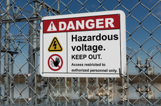
If an arc flash hazard exists, arc flash labels must be applied, with appropriate protective measures. Each label requires custom information that includes:
-
Calculated fault current value
-
Date of fault current assessment
-
Warning symbols for high-voltage areas
-
PPE requirements for nearby personnel
Proper labeling aligns with NFPA 70E and OSHA standards for safe work practices around energized equipment.
DuraLabel Fault Current Labeling Resources
Managing fault currents is a key aspect of maintaining electrical safety and compliance. Proper calculations help prevent system failures, ensure the correct selection of protective devices, and minimize downtime. Effective electrical load management plays a crucial role in mitigating risks associated with high fault currents, reducing the likelihood of equipment damage and hazardous incidents. Proper electrical labeling ensures that electrical systems remain compliant and workers are protected. Critical power system safety depends on accurate fault current calculations, which guide the selection of protective devices and safety protocols.
To help facilities implement a safer and more compliant electrical system, DuraLabel offers expert guidance and high-quality labeling solutions. Download our free Arc Flash Quick Action Guide today to learn more about effective fault current management and best practices for workplace electrical safety.
Read Next:
From Flash to Ash: Understanding Arc Flash and Preventing Them
Energize Workplace Electrical Safety Plans
.webp)

Available Fault Current
The National Electric Code, or NEC, requires that equipment be marked with the available fault current, and ...
Read
Stop Electrical Explosions Before They Start with Circuit Analysis
What Causes an Arc Blast? Electricity powers nearly every industrial process—but when something goes wrong, ...
Read
NEMA Studies Switching Current in Buildings
The National Electrical Manufacturers Association is looking into the impact of DC electrical distribution ...
ReadTake Action

Print Your Own Signs

Free Label Design Software
%20(1).webp)